


After having seen how to define the trajectory, we will now ask ourselves how to follow it.
In this article, we will briefly study the operation of the different means of navigation, and we will see that it is a bit of a history, even if not all light aircraft have the latest technical developments and still sail like Mermoz (or almost)!
THE MAGNETIC COMPASS
The first navigation instrument was certainly the magnetic compass.
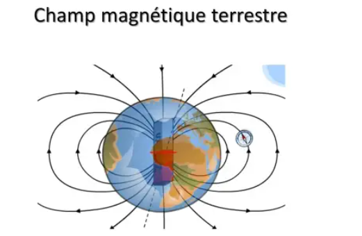
It was the Chinese who, around the year 1000, were the first to use a magnet to orient themselves using the earth's magnetic field.
It also seems that migratory birds use this earth's magnetic field for their long journeys...
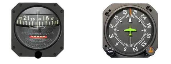
The magnetic compass consists of a heading rose slaved to a permanent magnet.
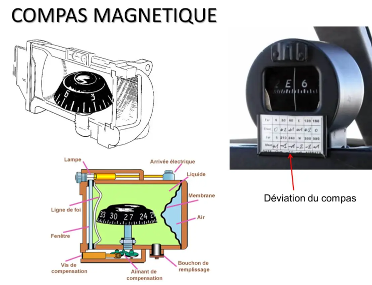
Under its heading line, we can read the magnetic heading followed by the plane, or more precisely what we call the compass heading. It therefore seems the ideal tool for following, at a constant heading, a rhumb line!
But the magnetic compass has several flaws.
First of all, the magnetic compass being essentially composed of a magnet, it is sensitive to the metallic masses and the electromagnetic fields of the aircraft, which taints its indications with an error called compass deviation. It is measured periodically on each aircraft by maintenance services and indicated on the instrument.
It will therefore be necessary to correct the compass reading for this deviation to determine the real magnetic heading.
Furthermore, its reference is not true North, in the direction of the North Pole, but a magnetic North Pole whose geographical position is not exactly that of the North Pole.
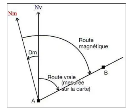
The difference between Nv and Nm is called the magnetic variation Dm or magnetic variation in English (VAR). Its value, indicated on maps, varies from one place to another on the globe, and changes gradually from year to year.
It is denoted E or W depending on whether magnetic North is east or west of the true North Pole.
To follow, with such a compass, the true route Rv measured on the map, it will be necessary to correct it by the value of the declination to find the magnetic route Rm. On a longer rhumb line course, the declination will change. We will therefore have to evolve the Rm to stay on the road. Conversely, if we keep a constant Rm, we will not exactly follow the rhumb line.
If the declination is currently very low or even zero in France, it can reach more than 20° in certain regions, in Newfoundland, in Canada, for example, and even 40° or 50° in the north of the country (34°W at Iqaluit)! In this case, we cannot neglect it…
For more information on this subject, you can refer to the article on on-board instruments: http://www.flightsim-corner.com/aller-plus-loin/navigation/instruments-de-bord
The magnetic compass is oriented according to the horizontal component of the Earth's magnetic field. Its rose is kept approximately horizontal thanks to a counterweight or with a float system.
In polar regions, due to the shape of the flux lines of the Earth's magnetic field, the horizontal component becomes very weak. We consider that when this horizontal component becomes less than 6 micro teslas, the compass indications are no longer valid.
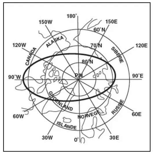
The geographical areas corresponding to this situation are indicated on the maps representing these regions.
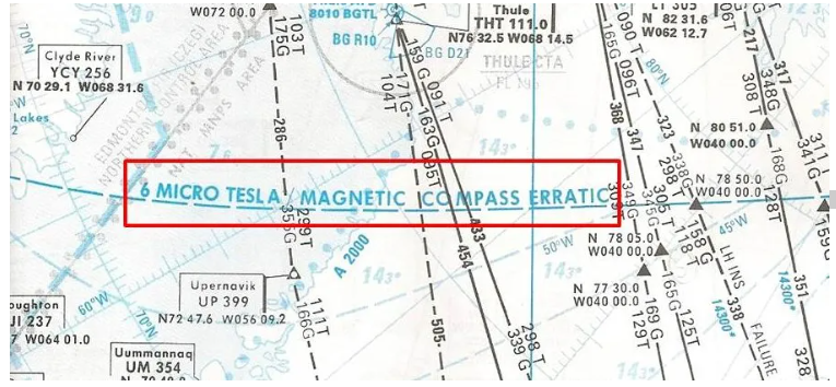
FSX or P3D do not seem affected by this problem, and therefore do not simulate the loss of validity of the magnetic heading in these inhospitable regions...
In addition, magnetic compass indications are unstable and sensitive to turbulence. When the plane is tilted, the magnetic sensor is no longer horizontal, which disrupts the measurement. Furthermore, the magnetic compass equipped with a counterweight is sensitive to acceleration.
As a result, its indications are only valid in stabilized horizontal flight, which makes it difficult to use in turns and unusable to guide the plane through an autopilot for example.
THE CAPE CONSERVATIVE
To remedy a certain number of defects of the magnetic compass, the qualities of the gyroscope were used. This has the advantage of keeping a fixed direction with respect to absolute space, which has advantages and disadvantages.
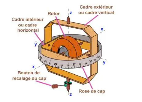
The heading conservator, or directional gyro, is equipped with a gyroscope with two degrees of freedom (two frames) whose axis of the top is kept horizontal.
Unlike the magnetic compass, its indications are very stable and it can be used perfectly when turning. On the other hand, it must be aligned with a North reference, magnetic North, true North or grid North. In addition, it must be readjusted often because it will only keep this calibration reference for a short time for several reasons:
- First of all, the gyroscope is not perfect, it will not forever keep its direction in relation to absolute space: we call this mechanical precession which will depend on the mechanical quality of the gyroscope. Then, the earth rotating on it -even, if the axis of the gyroscope remains pointed towards a star, for example (absolute space), it will therefore rotate in the same way that the stars seem to rotate in the sky: this is astronomical precession. Its value depends on the latitude at which we find ourselves, and is worth 15° x sin L per hour, zero at the equator but maximum at the poles. It turns the North of the gyro to the right in the northern hemisphere and to the left in the south, even if the plane remains stationary on the ground! And if we also want it to indicate true North (or magnetic north at constant declination), we should also correct the convergence of the meridians when we move on the earth: this is the precession map!
It is of course too complicated to take care of all that when you are doing a short VFR flight! But, it is good to know that all these precessions degrade the accuracy of the heading displayed by your heading curator. When they are in the same direction they add up, and we can arrive at important values! It is therefore necessary to readjust the course conservative very regularly. Generally, we use the heading of the magnetic compass to reset the heading curator.
FSX, P3D and X-Plane can simulate these precessions provided the function is activated. In this case, it is therefore necessary to readjust the directional gyro regularly…
THE GYROMAGNETIC COMPASS
Principle
We thus discover that the qualities of the directional gyro practically correspond to the defects of the magnetic compass and vice versa. It was therefore imagined, quite naturally, to combine the two to design the gyromagnetic compass.
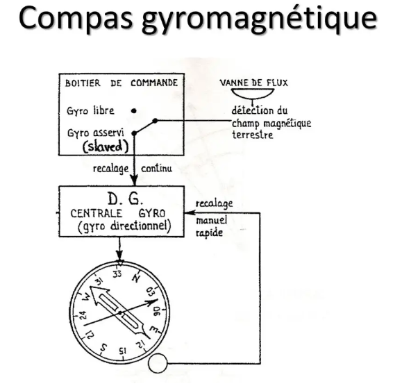
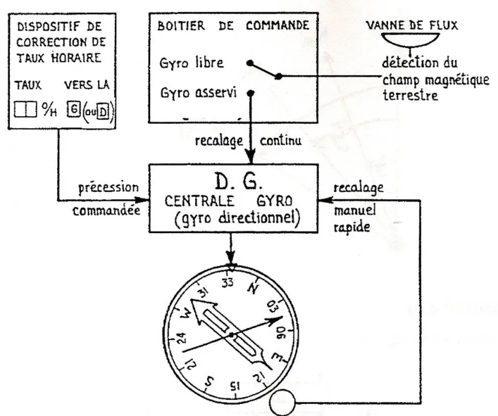
In this case, the gyroscope heading is automatically synchronized with the magnetic heading. There is no longer any need to readjust the gyro. The magnetic sensor is a flow valve, most often installed at the end of the wing to move away from ferrous masses and electric fields, which delivers magnetic heading information in electrical form and which synchronizes the gyroscopic heading through 'a compass coupler. This is SLAVED mode.
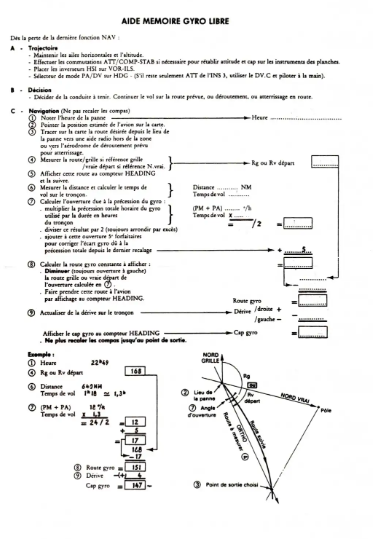
To be able to use this gyromagnetic compass in the 6 micro teslas zone, it is planned to disengage the synchronization with the magnetic heading: this is the DG or free gyro mode, where the system functions exactly as a heading curator. The difference is, however, that this system being more sophisticated and therefore more expensive, the gyroscope is of good quality with very limited mechanical precession.
The POLAR PATH type compass
The most elaborate forms of this system were found on long-haul aircraft which preceded the arrival of inertia power plants.
Thus, the B707 or the DC8 were equipped with a Polar Path type gyrocompass system, which made it possible, in Free Gyro mode, to apply a time correction rate to the gyro compass. We could then follow, at a constant gyro heading, the map line of any map, and in particular the transverse or oblique Mercators.
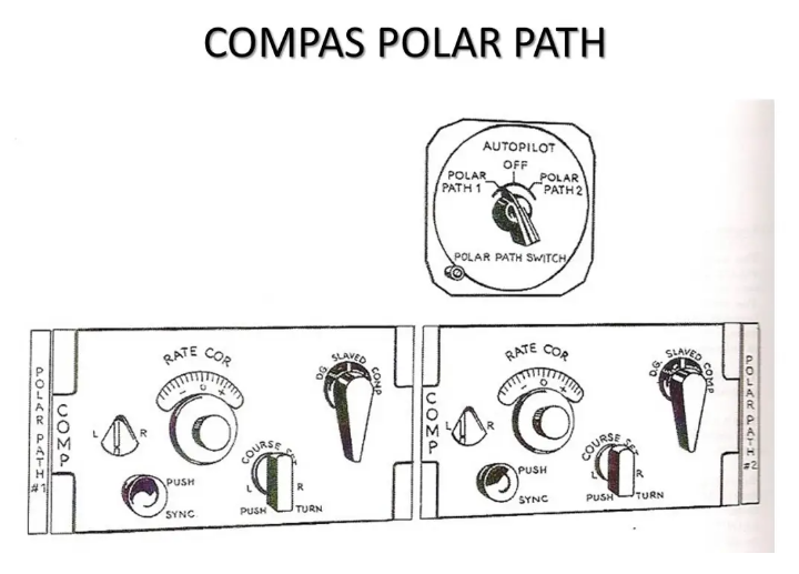
But for that, it was better to have on board an experienced navigator, who periodically reset his navigation by other means such as long-range radio means, or astronomical navigation: a matter for professionals therefore!!!
The planes which followed this first generation of long-haul jets such as the B747-100/200/300 or the DC10 were still equipped with this type of system but the gyroscopic heading information came from the azimuth gyro of the platforms at INS inertia.
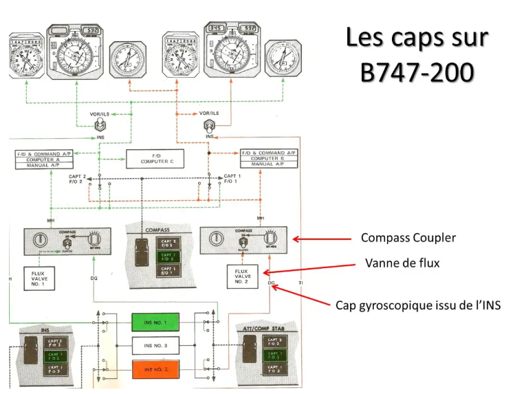
The compass coupler was still present with its two possible modes SLAVED or DG (click on the image to enlarge).
The DC10 had this particularity, with its Litton 58 INS, of delivering a gyro heading corrected for mechanical precession (very weak, a few tenths of degrees per hour) and astronomical precession, which had the effect of canceling the rotation of Earth. We therefore followed, at a constant gyro heading, a straight line in relation to the earth, that is to say an orthodromy.
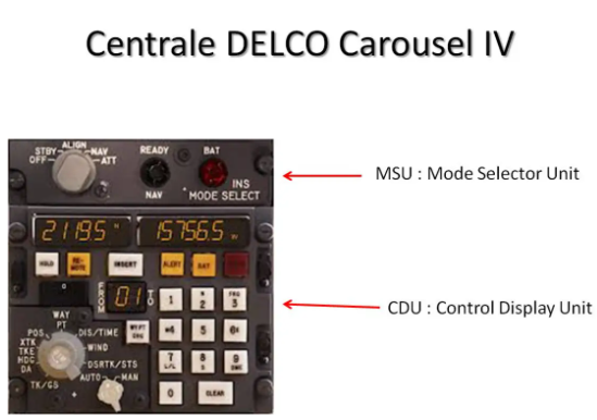
On B747, the INS DELCO Carrousel IV did not present this particularity, and their mechanical precession, which was measured during alignment and stored in memory, could reach very high values, of the order of 12°/h, which added to the astronomical precession could reach up to 27°/h in the polar regions!!!
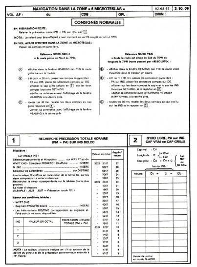
A very complicated emergency procedure made it possible to know this mechanical precession and, thanks to a special sheet, to calculate the gyro heading to take to exit zone 6 micro teslas, as an emergency.
We understand better why it was necessary to do a specific course before venturing into such areas.
As for the experienced navigator, he was disembarked, of course, with the arrival of the INS… that’s progress!!!
TAKING THE WIND INTO ACCOUNT
In everything we have just seen, we have only been concerned with staying on course, as precisely as possible. But the trajectory to follow is a road! And we obviously cannot consider flying only on windless days!
The speed triangle
The effect of the wind is highlighted in the speed triangle: the speed vector relative to the air is oriented according to the heading and its measurement corresponds to the TAS natural speed.
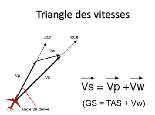
By making the vector sum with the wind vector, we obtain the ground speed vector oriented along the route followed. The angle between heading and course is called the drift angle.
This beautiful drawing is very easy to trace on paper, much more difficult to do in flight! And above all, you need to have fairly precise knowledge of the wind.
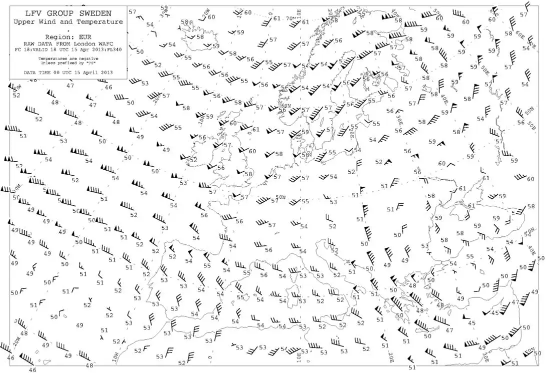
In terms of pre-flight preparation, weather services provide forecasts in the form of wind forecast maps at different altitudes.
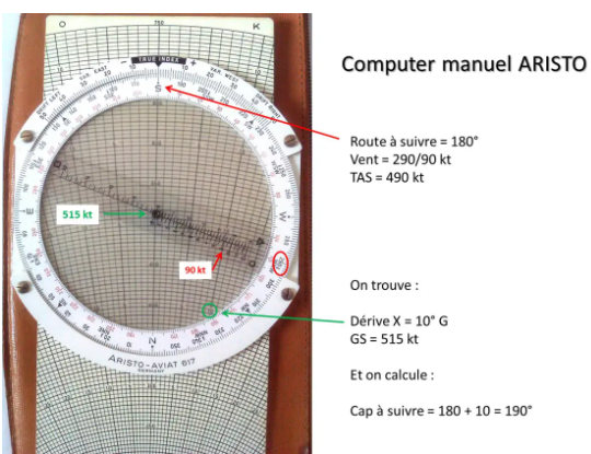
Precise mathematical methods, more approximate mental calculation, or the use of manual or electronic computers then make it possible to find the drift angle and ground speed. We will therefore know what heading we must take to follow the planned route, as well as the ground speed at which we will travel said trajectory.
Here, for example, is how to calculate drift and ground speed using the specialized ARISTO computer.
But this is just a prediction! And everyone knows that there is always a margin of error, sometimes significant, between prediction and reality...
It was therefore necessary to find ways to assess the wind experienced during flight. And that’s not very easy!
For the drift, if you are lucky enough to be in sight of the ground, you can evaluate it visually by observing marks in the axis of the plane: not very precise...
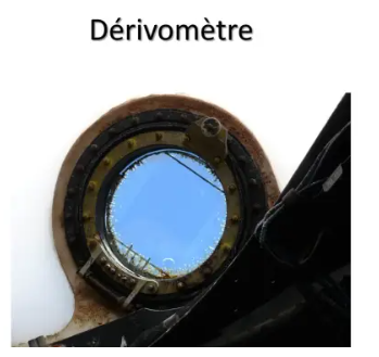
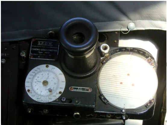
The derivative meter
The driftometer, by following a ground marker on a reticle, made it possible to measure the drift... in good weather and rather during the day and above the ground!!!
For ground speed, certain derivometers (called kinemo-derivometers) also made it possible to evaluate it…
And then there is always the timing of a course which allows it to be calculated. But we immediately see that the precision will not be there, and even practically impossible on long-distance maritime journeys!!!
Isobaric navigation
Another system, long abandoned, was used at sea to determine crosswind and drift. This is what we called isobaric, or pressure, or D-factor navigation.
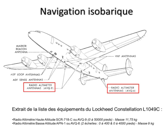
It was necessary to have a high altitude radio altimeter capable of measuring the real altitude which, compared to the pressure altitude (factor D) made it possible to calculate the transverse component of the geostrophic wind (theoretical wind) and therefore the drift... Another matter of professional navigator!
Doppler Browser
More precise electronic systems have also emerged. This is the case of the Doppler effect browser.
When you find yourself at the edge of a car circuit, the sound produced by the arriving car changes tone when it passes in front of you and moves away: it is the Doppler effect which causes the frequency of the sound emitted by the mobile is modified by its speed. You may have been a victim without knowing it since some road radars work on this principle!
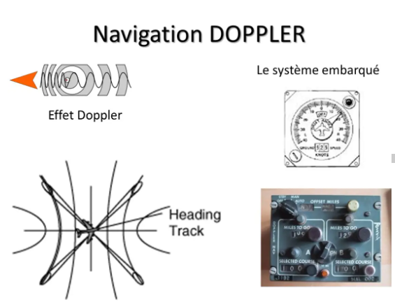
It was also used in aeronautics to measure the ground speed of aircraft and, by combining several receivers, to also measure drift. The instrument at the top and right indicated ground speed and drift.
It was possible to couple it to a dead reckoning totalizer (bottom right) and the system could then be used by the autopilot (DC8 UTA).
But the precision was, despite everything, not exceptional, and the too smooth surface of certain grounds (calm sea for example) caused the return signals to be lost. Navigation then continued with the last measured values which were kept in memory…!!!
OTHER MEANS OF NAVIGATION
We therefore understand that it was necessary, at that time, to have other means available to recalibrate navigation, at least periodically, to claim suitable precision...
Astronomical navigation
One of the simplest means of adjustment to implement was, by analogy with the navy, astronomical navigation. But, unlike boats, the high cruising speed of planes, particularly jets, will significantly complicate the problem: a crew member was specially assigned to this work which required great rigor in the application of procedures.
For pressurized planes, a periscopic sextant was used, to have a panoramic view above the plane, equipped with a system by measuring the height of the star during the two minutes that the sighting on each star lasted.
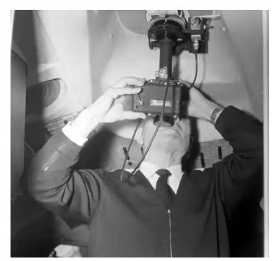
Here again, the precision was very relative, and only allowed a discrepancy to be noted a posteriori, without being able to anticipate the rest of the flight...
Long-range radio means
Apart from the classic radio means, VOR and NDB, which could be used up to the limit of their useful range, around 200 Nm, there were long range means which made it possible to reset navigation by dead reckoning.
The Console
The Consol was an improved radio beacon that transmitted in the 250-350 kHz band. Depending on the position of the plane in relation to the beacon, we received a certain number of points and Morse code lines that had to be counted, which corresponded to position locations plotted on the maps.
A beacon of this type was located in Brittany, at Ploneis near Quimper. She was arrested in 1970.
The Loran
Loran (Long RAnge Navigation) is a hyperbolic positioning system comprising two transmitters, a master and a “slave”. Positioning is done by measuring the difference in the propagation times of the signal emitted by the two transmitters, the locus of points with the same difference forming a hyperbola.
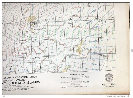
The hyperbola networks of the different pairs of transmitters were indicated on the navigation maps.
Several versions have been developed: Loran A, Loran C, Loran E. Loran C is still in service as a backup means for boats in the event of a GPS failure.
Just like astronomical navigation, the use of these radio means on board aircraft required the presence of a navigator and, for Loran, specific reception equipment...
But as for astronomical navigation, we only have, here again, means of controlling the position a posteriori, which only make it possible to recalibrate the navigation which is carried out, a priori, by dead reckoning, with all the hazards which necessarily degrade the precision.
The OMEGA system
A quick word in passing about a system which only made a brief appearance in the inventory of long-range radio resources. The OMEGA system, set up by the American army at the end of the 1960s, in the midst of the Cold War, operated on the same principle as LORAN, but in a much lower frequency range, the VLF (Very Low Frequency) band. ), around 12 kHz.
Eight transmitters made it possible to cover all of the world's oceans. Only one was on French territory, on the west coast of Reunion Island. The height of the antenna masts, a little over 400 m, often made them the highest constructions in the country...!
The installation, on board the planes, included a fully automatic receiver and a CDU quite comparable to that of the INS, which we will talk about shortly after.
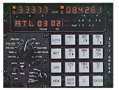
The nominal accuracy was around 1.5 Nm, but propagation problems in this frequency range could degrade it significantly. Nevertheless, the OMEGA system was certified as a means of navigation in the MNPS area of the North Atlantic, in association with an INS system.
The arrival of satellite systems such as GPS very quickly spelled the end of the OMEGA system for civil aviation. As the maintenance costs of the ground stations were very high, it was decided to stop them in 1997.
INERTIA NAVIGATION
The ideal would therefore be to be able to orient the plane so that it follows the chosen route directly without needing to go through the heading, and to know how to measure the real speed in relation to the ground, whatever the flight conditions... !
It is inertial navigation that will provide the solution.
This is not a recent idea since such a system had already been used to guide missiles, notably the German V1 and V2, during the Second World War. The difficulty was to produce equipment that was sufficiently reliable and precise to be able to be used during flights lasting several hours in the context of everyday operations.
Principle of operation
The principle is to constantly measure the horizontal accelerations experienced by the plane then, by integrating them with respect to time, a first time we obtain the speed, and a second time we obtain the displacement on the surface of the earth.
On two perpendicular axes:
- Measurement of acceleration γCalculation of speed: v = γ t v0Calculation of displacement: x = ½ γt² v0t x0
To put it simply, acceleration measures the rate of change of speed: with an acceleration of 2 m/s/s or 2 m/s², if the initial speed v0 is 7 m/s, one second later it will be of 9 m/s.
The same goes for speed which measures the rate of change of position. If you move away from your starting point x0 at a speed of 10 m/s, one second later you will be 10 meters further away.
If we indicate to the system, during the alignment phase, the exact position of our starting point, and if we measure the accelerations in two perpendicular directions, we will therefore be able to permanently know in which direction and at what speed we are moving, and finally where we are. It's nothing more than the principle of esteem but applied to very specific systems.
The great difficulty lies in the necessary precision of the accelerometers, and in their positioning relative to the earth. For this last point, it is again the gyroscope that will be used.
INS inertia platforms
The first systems dedicated to civil aviation appeared in the 1960s.
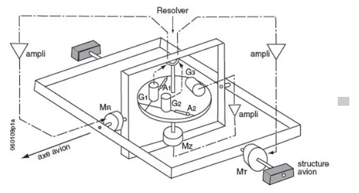
In the INS system (Inertial Navigation System), two accelerometers A1 and A2, at 90° relative to each other, are installed on a platform held horizontal by three gyroscopes G1, G2 and G3. Accelerometers therefore only measure accelerations in the horizontal plane, the only ones of interest to navigation.
Solutions will need to be found to resolve two main difficulties:
- keep the platform perfectly horizontal so as not to measure parasitic accelerations correctly orient the accelerometers relative to north. The solution chosen will rather be to determine their current orientation by calculation rather than orienting them physically: this is what we call the wandering azimuth.
The main manufacturers took slightly different approaches to achieve the desired precision in platform stabilization.
The Littons installed on B707 or DC8 and, later, on DC10 were equipped with extremely precise gyroscopes, a real clockwork mechanism!
Delco, with the Carousel IV which equipped most of the B747 and Concorde, opted for a platform rotating on itself, at constant speed, and which measured and corrected the mechanical precession of gyros which were much less precise, as we have seen more high.
The alignment phase makes it possible to place the platform horizontally by detecting gravity, and to calculate the orientation of the accelerometers by detecting the earth's rotation vector. It is during this phase that it is necessary to indicate to the system the starting point of the navigation by inserting the position of the aircraft parking station.
The INS navigation centers provide a lot of information on current navigation:
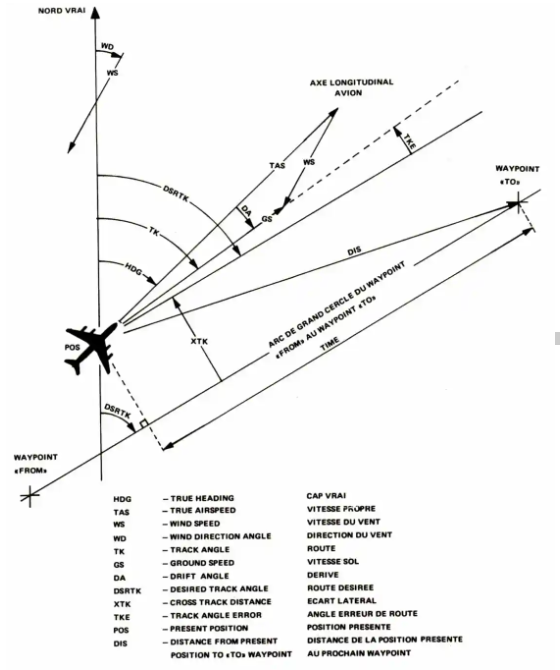
The names and acronyms may vary from one system to another but we almost always find the same measured or calculated data.
But these are very fragile and very expensive precision mechanisms, both for purchase and maintenance…
STRAP DOWN Systems
The current concept called “Strap Down” or orientation detection appeared later, with gyrolasers. The latter emit laser radiation which describes a closed path, triangle or square.

We measure the position difference of the ray on arrival which makes it possible to measure the movements of the plane and therefore to deduce its position in relation to the earth. It is no longer gyroscopes which stabilize a platform but gyrometers which measure the movements of the plane.
In the IRS (Inertial Reference System), this time there are three accelerometers which are fixed directly in a reference specific to the aircraft.
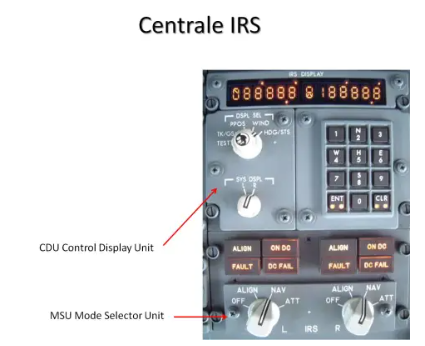
Thanks to three laser gyros, the computers are able, at any moment, to determine the position in space of each accelerometer, and to deduce the accelerations in the horizontal plane, and therefore the ground speed vector and the displacement on the surface. of the earth.
In both cases, these systems are therefore capable of directing the aircraft on a ground trajectory. The basic data which are the speed vector (true course ground speed) and the instantaneous position are used within a computer to guide the plane on the trajectory defined by the crew. At the beginning these were autonomous systems capable of guiding: Litton 51 and Delco Carousel. For Delco, there was also the possibility of mixing positions and making position adjustments from DME.
The Littons of the DC10 and the current IRS only provide the basic elements for AeraNav or FMS computers which manage the trajectory globally with all the available systems.
The accuracy of an inertial navigation system will depend on the time elapsed since the start of navigation. It can reach 1 Nm/h without any adjustment.
If a breakdown occurs on an inertial system, even very briefly, the instantaneous position is lost, the machine no longer knows where it is!!! To protect against possible electrical failures, inertial systems are equipped with a self-contained battery.
There is also an ATTITUDE function which allows you to retrieve, if necessary, attitude information from an ADI or a PFD, and gyro heading information to be used as a heading conservative, and therefore to be readjusted periodically...
In this navigation unit, heading unit inertial unit, the remaining weak link was the measurement of the magnetic heading always used in departure and arrival procedures or in radar guidance. With the arrival of Strap Down platforms and the increasing power of computers, the idea arose to do without flow valves and compass couplers, which was done with the Airbus A310 in the early 1980s.
Apart from the emergency compass, there is no longer any sensor of the Earth's magnetic field today. The magnetic headings displayed on the PFD or ND screens come from the true heading measured by the IRS to which the value of the magnetic declination stored in the Data Base is added. Additionally, there is a way (Norm/True reverser on B747-400) to switch to a true heading display for navigating in polar regions. We can certainly imagine that in the not too distant future we will no longer be talking about magnetic headings!
With these systems, we achieve the ultimate goal of the navigator: to be able to complete any route autonomously, with great precision, whatever the flight conditions. And what's more, we navigate as quickly as possible while always following a great circle!
NAVIGATION PAR SATELLITE
It's impossible these days to talk about navigation without mentioning GPS, omnipresent in our modern lives, whether in cars or in most smartphones!
More generally, we should talk about GNSS (Global Navigation Satellite System), making it possible to determine the position using a constellation of satellites. Two systems are operational today:
- the American NAVSTAR GPS system, more commonly called GPS for Global Positioning System; the Russian GLONASS system, for GLObal NAvigation Satellite System.
The European GALLILEO project, more modern and more precise, has fallen far behind schedule, and is therefore not really operational...
They all work on the same principle: measuring the travel time of signals emitted by satellites determines spherical position locations.
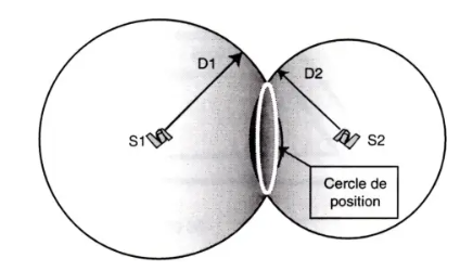
The interception of two of these spheres gives a position circle.
The reception of a third satellite makes it possible to determine two possible position points.
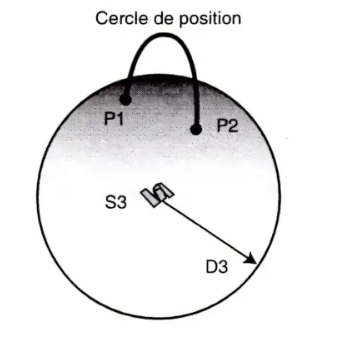
In practice, a fourth satellite will be necessary to obtain good precision in the position and adjustment of the clock, and even a fifth to control the coherence of the system.
The average precision of standard GPS is around 15 m in 95% of cases, which represents 0.008 Nm, therefore quite sufficient for RNP (Requested Navigation Precision) up to 0.3 inclusive.
Most on-board systems, in fact, only use the American NAVSTAR GPS system…
In air transport, satellite navigation systems are only used to realign autonomous, inertial navigation systems. They are not used as primary navigation systems but as a priority means of alignment, due to their precision, for several reasons:
- the GPS and GLONASS systems are military systems directly dependent on the owner states, which can therefore interrupt or degrade them at their sole initiative certain regions of the world are poorly covered (polar regions) there are periods when the reception redundancy of the satellites is insufficient to ensure the best precision.
It is, moreover, always possible to deactivate the alignment of the systems by the GPS(es)…
THE FMS
Initiated a long time ago with the AeraNav of the DC10 which dates from 1971, we have now reached globalized management of the trajectory thanks to the FMS (Flight Management System). On DC10, we had done with the means of the time: calculator with 48 KB of RAM, Data Base on magnetic tape cassette, not practical and very expensive... hence the failure of the moment. But the principles were there and have been adopted almost identically today!!!
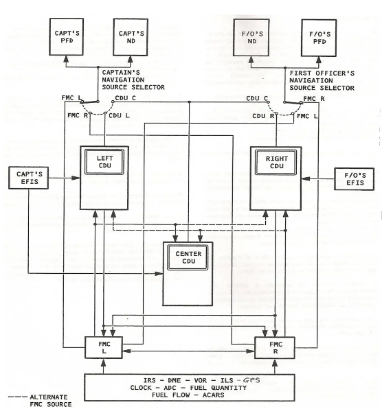
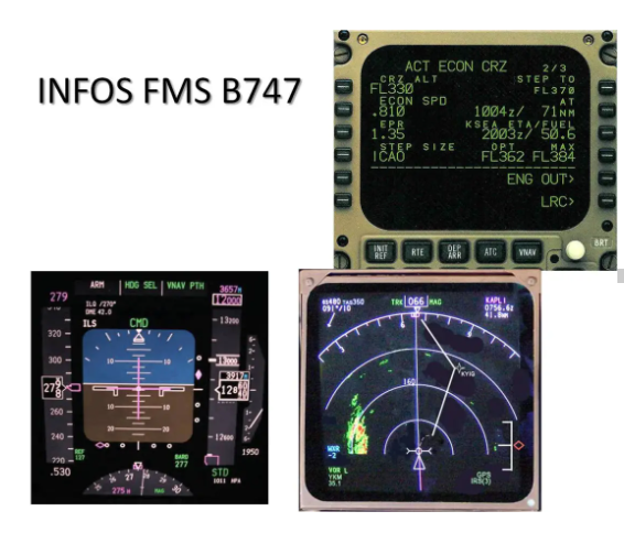
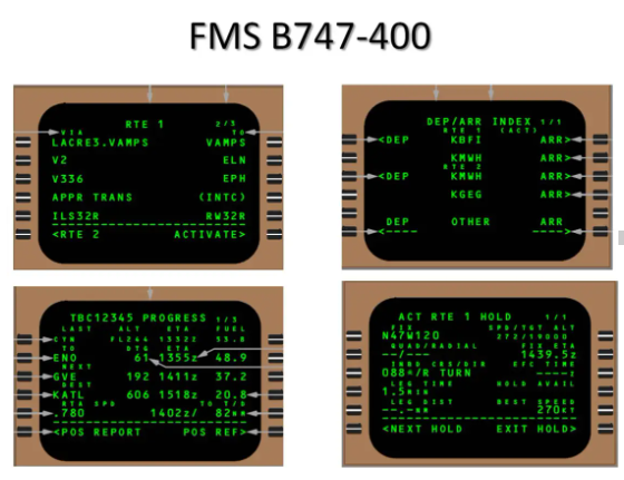
On B747-400, example presented above, the FMS system includes 2 FMC (Flight Management Computer) calculators which collect all the available information to calculate the horizontal (L-NAV) or vertical (V-NAV) trajectories, allowing management fine-grained fuel consumption, among many other functions… and distributes its information to both the CDU and the PFD and ND screens.
To stay in the area that interests us today, horizontal navigation or lateral navigation LNAV, the FMS will first use the IRS which provide the Cv, the Rv, the GS and the instantaneous position. The positions of the different available IRS will be mixed to have a most probable position (triple mixing), and this will be adjusted by the available radio means, at the forefront of which today is GPS. But as much as we can fly without GPS, we can hardly do without at least one IRS!!!
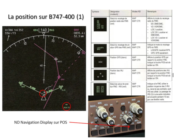
We can get an idea of the precision of the different components by observing the ND which indicates, in the example here, that we are in Triple Mixing, IRS (3) and VOR DME registration (VD). By pressing the POS button on the EFIS control box, three small stars appear representing the inertial positions of the three IRS in relation to the position of the FMS symbolized by the top of the triangle, representing the nose of the aircraft.
To avoid alarms due to excessive longitude deviations, when the latitude exceeds 84°N or 84°S, the triple mixing function is automatically deactivated.
If one or two GPS are available, we will also have their position, generally attached to the nose of the plane since this is the preferred means of alignment.
When the latitude exceeds 88.5° N or S, GPS alignment, if still available, is automatically deactivated.
The B747-400 FMS is not capable of managing the vertical shift of the poles. It is prohibited to fly at a latitude greater than 89° North or South.
You can also be informed of the position accuracy on page POS 2/3 of the FMS.
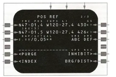
We find in particular the position of the FMC and its source of adjustment, here the left GPS, the IRS position, here the Triple Mix position (3), and the precision of the position, Actual Navigation Precision ANP evaluated here at 0.05 Nm .
On the POS 3/3 page, you can find out the position of each IRS and each GPS.
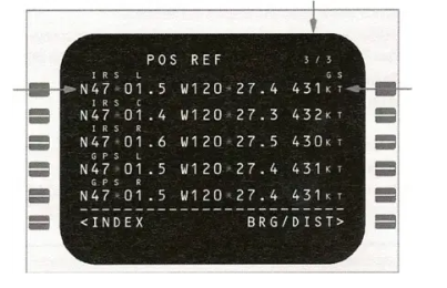
By pressing BRG/DIST, the difference in bearing and distance from the FMC position will be indicated, i.e. the values which position the symbols on the ND screen.
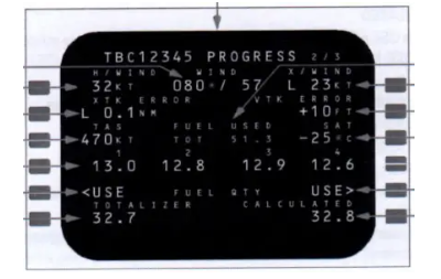
We find, on the PROGRESS 2 page, some of the information provided by the inertial units: the wind with cross and on-axis components or the XTK cross track.
The FMCs also make it possible to carry out surface navigation (RNAV) thanks to a database, which makes it possible to follow airways by constructing a flight plan, departure and arrival trajectories SID and STAR, to make approaches, OFFSETs, waits at the racetrack, etc.
In the event of a breakdown of both FMCs, the MCDUs make it possible to carry out emergency navigation which is similar to what was done with the INS.
CONCLUSION
We see that, little by little, we have managed to approach the ideal system, one which allows navigation in any part of the world, with greater and greater precision, in all conditions. All this has made it possible to greatly secure air traffic, but also to reduce the spacing between aircraft and therefore to increase the capacity of airspace, and to compensate for the deficiencies of land radio guidance means. The most modern systems now allow approaches to be made with increasingly lower minima.
Even if all this can give the illusion of great ease or that the cards are no longer useful, it is always useful to know how it works and how we could do without it in the event that, unfortunately, a breakdown occurs. would intervene. This was the modest ambition of this presentation…